Where do you put your bypass capacitors?
I’m not asking about where to put them in the PCB layout. On the finished PC board, bypass capacitors need to be strategically located as per the chip and noise source data sheets recommend. Rather, I’m curious as to your thoughts on where to put them on the schematic? In this schematic clip, I’ve grouped them altogether up on the top of the schematic. Doing so makes for a clean and well organized sheet. Sometimes, though, I’ll place them in the schematic right up next to the chip, as they would be on the physical PC board layout. I find that practice to be preferable when there are bypass caps that need to be of different values. Electrically, both practices are equal, so I think it more or less comes down to individual style or convention.
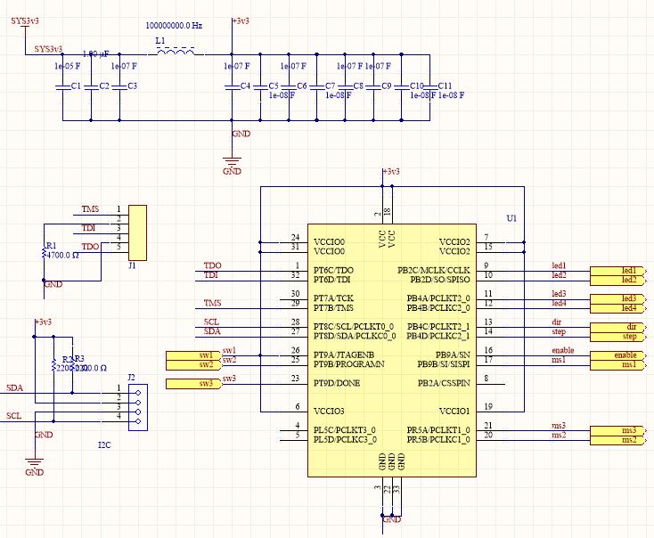
Sometimes I’ll let the schematic symbol take the lead. Here, the IC symbol has pins grouped by functionality rather than in numerical order as they would be on the physical chip. If the pins on the symbol were in numerical order, to me, it makes more sense to locate the bypass capacitor next to the power/ground pins on the IC symbol. With this style of symbol, that doesn’t seem to be as important.
On the other hand, I’m probably more likely to forget a capacitor or put it in the wrong place during the PCB layout phase if I follow the practice illustrated in this clip. What about you? How do you place your bypass capacitors? Is it a matter of style, or is one way or the other best practice?
Duane Benson
Six of one and 0b00000110 of another
Once you’ve placed all of those capacitors and finished up the layout, visit www.screamingcircuits.com and get a quote on having us put them (and your other parts) on your PC board.